
Page 3 - Demo
P. 3
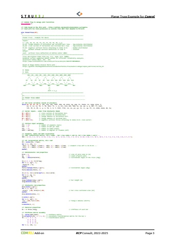
Planar Truss Example for Comrel Add-on RCP Consult, 2022-2026 Page 3//! Global flags to manage plot facilitiesStrurelPlot=1;StrurelPlotName=\StrurelPlotType=\StrurelPlotMode=3;//! Code based on Max Ehre work - https://github.com/maxehre/polynomial_surrogates//! Used with his kind permission as version from 2017 that adapted to Strurel.proc PlanarTruss(XP);/*============================================================================ Planar Truss - Example for Gauss============================================================================ Inputs: X = [A1, A2, E1, E2, P1, P2, P3, P4, P5, P6, u_y] E1,E2: Youngs modulus of horizontal and inclined bars resp. - log-normally distributed A1,A2: cross section of horizontal and inclined bars resp. - log-normally distributed P1-P6: negative vertical forces attacking in nodes 8-13. - Gumbel distributed u_y: maximal allowed vertical deflection in node 4. - constant Output: uout: vertical truss deflection at bottom center (N04)============================================================================ Truss description taken from Lee, S.H., Kwak, B.M. (2006). Response surface augmented moment method for efficient reliability analysis. Structural Safety 28(3), 261 - 272. https://www.sciencedirect.com/science/article/abs/pii/S0167473005000421 Based on Diego Andr%u00e9s Alvarez Mar%u00edn work - https://github.com/diegoandresalvarez/elementosfinitos/tree/master/codigo/repaso_matricial/cercha_2d N: Nodes R: Rods============================================================================ N13__R4___N12__R8___N11__R12__N10__R16__N09__R20__N08 /\\ /\\ /\\ /\\ /\\ /\\ / \\ / \\ / \\ / \\ / \\ / \\ R1 R3 R5 R7 R9 R11 R13 R15 R17 R19 R21 R23 / \\ / \\ / \\ / \\ / \\ / \\ /___R2___\\/___R6___\\/__R10___\\/__R14___\\/__R18___\\/__R22___\\ N01 N02 N03 N04 N05 N06 N07 ||\\/ uout => u_y============================================================================*///!---------------------------------------------------------------------------//! Planar truss model//!---------------------------------------------------------------------------//! All local variables inside of procedurelocal A1, A2, E1, E2, P, nfe, ned, nnp, ndof, IEN, LM, Grid, ng, ang, t1, theta, l1, leng, Area, E, ke, K, co, si, Tb, T, TD, Kloc, fc, c, d, Kcc, Kcd, Kdc, Kdd, ac, ad, qd, a, q, NEL, TT, uout, tit, XY, b, DF, x, y, n, fd, l, X, Y, Xrot, Yrot, xo, xe, yo, ye, ll, cc, ww, tt, cn, minA, maxA, dA, Su, q;//! Vector inputs - order from Stochastic ModelA1 = XP[1]; // cross section of horizontal barsA2 = XP[2]; // cross section of inclined barsE1 = XP[3]; // Youngs modulus of horizontal barsE2 = XP[4]; // Youngs modulus of inclined barsP = XP[5:10]; // negative vertical forces attacking in nodes 8-13. (1x6 vector)//! Initial input variablesnfe = 23; // number of elements (bars)ned = 2; // number of dof per nodennp = 13; // number of nodal pointsndof = ned*nnp; // number of degrees of freedom (dof)//! Elements, nodes and dofs association//! IEN: connectivity matrix, nfe x nodes - bar 1 has nodes 1 and 13, bar 2 has nodes 1 and 2 ...IEN = {1 13, 1 2, 13 2, 13 12, 2 12, 2 3, 12 3, 12 11, 3 11, 3 4, 11 4, 11 10, 4 10, 4 5, 10 5, 10 9, 5 9, 5 6, 9 6, 9 8, 6 8, 6 7, 8 7};//! LM: localization matrix, nfe x dofLM = zeros(nfe, 2*ned);for n (1, nfe, 1); LM[n, 1] = IEN[n, 1]*ned-1; LM[n, 2] = IEN[n, 1]*ned; // element 1 has dof 1-2 & 25-26 ... LM[n, 3] = IEN[n, 2]*ned-1; LM[n, 4] = IEN[n, 2]*ned;endfor;//! Deterministic rod propertiesGrid = 4; // size of grid side in [m]ng = 12; // count of grid cellsang = atan(Grid/Grid); // inclination angle of the truss [deg]t1={1 0 -1 0}; t1=t1*ang;for n (1, ng/2, 1); theta=t1 | t1;endfor;theta=reshape(theta,1,ng*2); // inclination angle [deg]theta=delcols(theta,-1);l1={0 0}; l1[1]=Grid/sqrt(2); l1[2]=Grid;for n (1, ng, 1); leng=l1 | l1;endfor;leng=reshape(leng,1,ng*2); // bar length [m]leng=delcols(leng,-1);//! Stochastic rod propertiesArea=zeros(1,ng*2);for n (1, ng*2, 2); Area[n ]=A2; Area[n+1]=A1; // bar cross sectional area [m2]endfor;Area=delcols(Area,-1);E=zeros(1,ng*2);for n (1, ng*2, 2); E[n ]=E2; E[n+1]=E1; // Young's modulus [N/m^2]endfor;E=delcols(E,-1);//! Material propertieske = E.*Area./leng; // stiffness of each bar//! Stiffness matrix assemblyK = zeros(ndof,ndof); // stiffness matrixTb=arrayinit(nfe | 4 | 4, 0); // coordinate transformation matrix for the bar nTD = { 1 0 -1 0, // transformaion matrix 0 0 0 0,
